디지털 회로 설계를 입문하기위해 비교적 쉬운 인코더를 Verilog로 설계한다.
처음 작성하는 만큼 환경 구성에 대한 간단한 설명도 함께한다.
설치한 Vivado는 2022.2 ML이고 사용자의 환경에 따라서 굳이 최신버젼일 필요 없이 안정적인 버전을 찾아 사용하면된다.
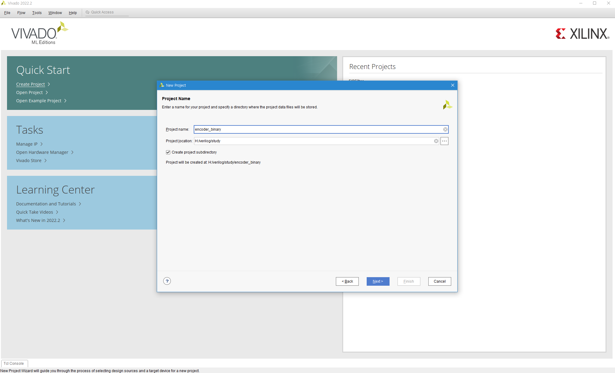
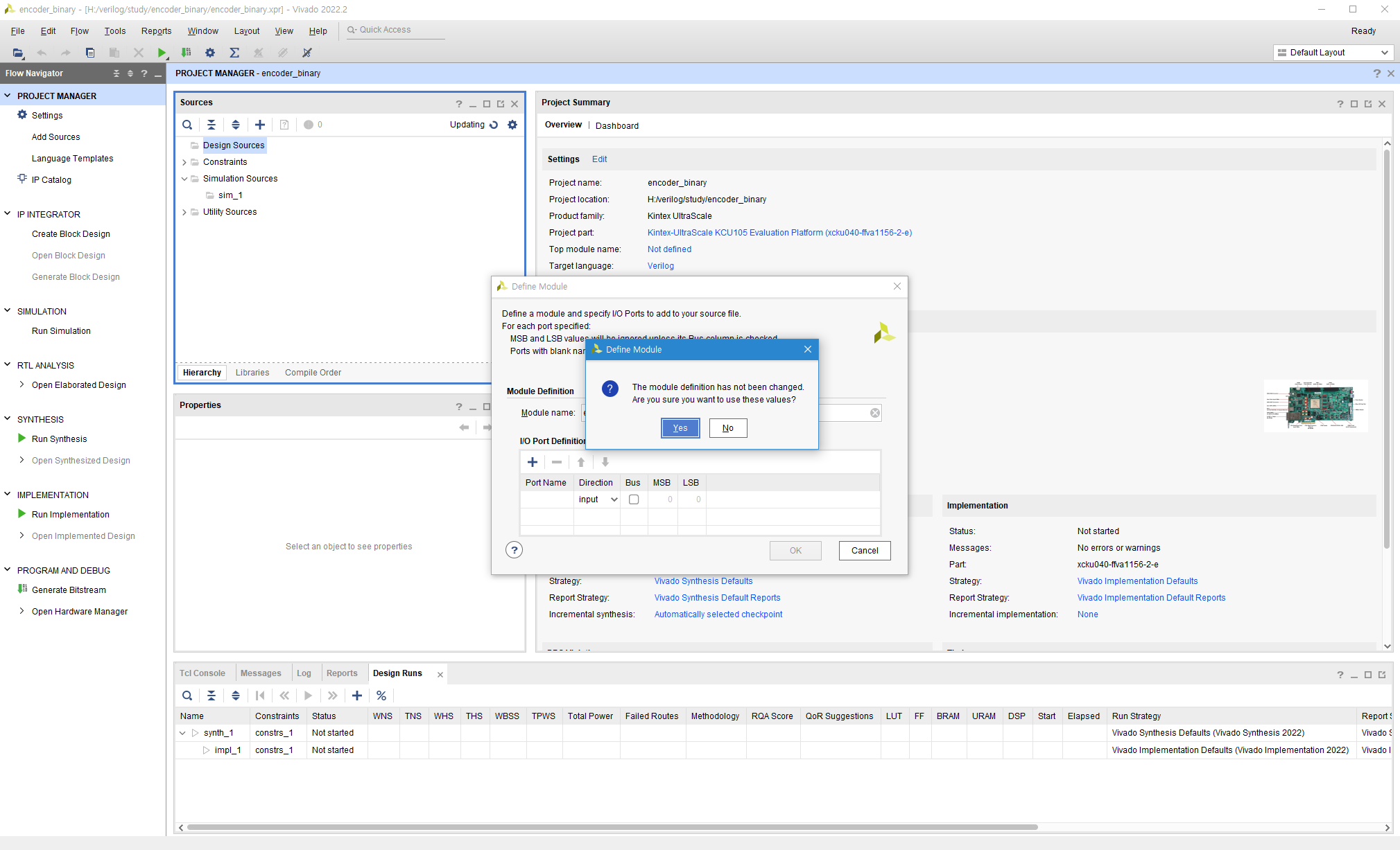
Vivado를 처음 키고 Create Project를 누른 모습
Project 명을 설정
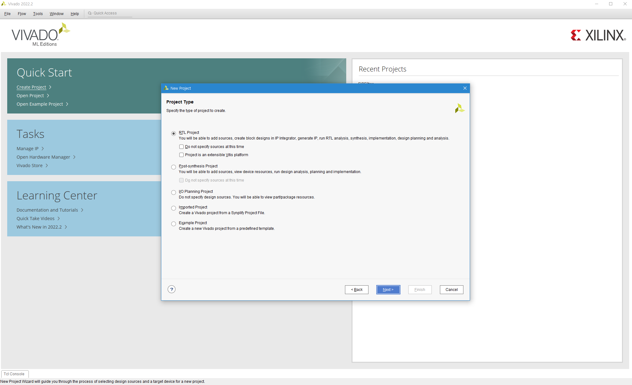
Next
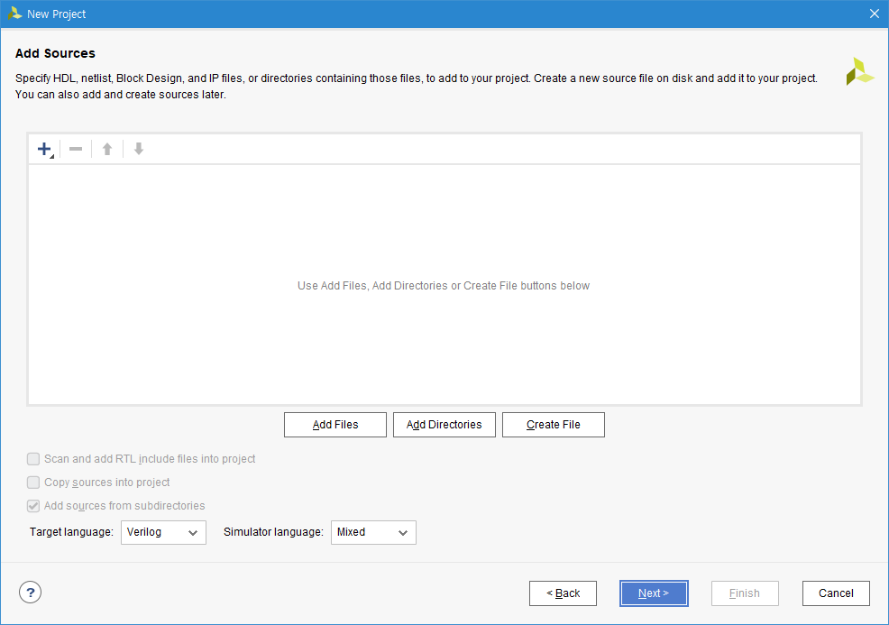
Next
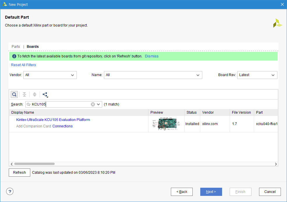
사용하고자 하는 Board 및 FPGA 선택
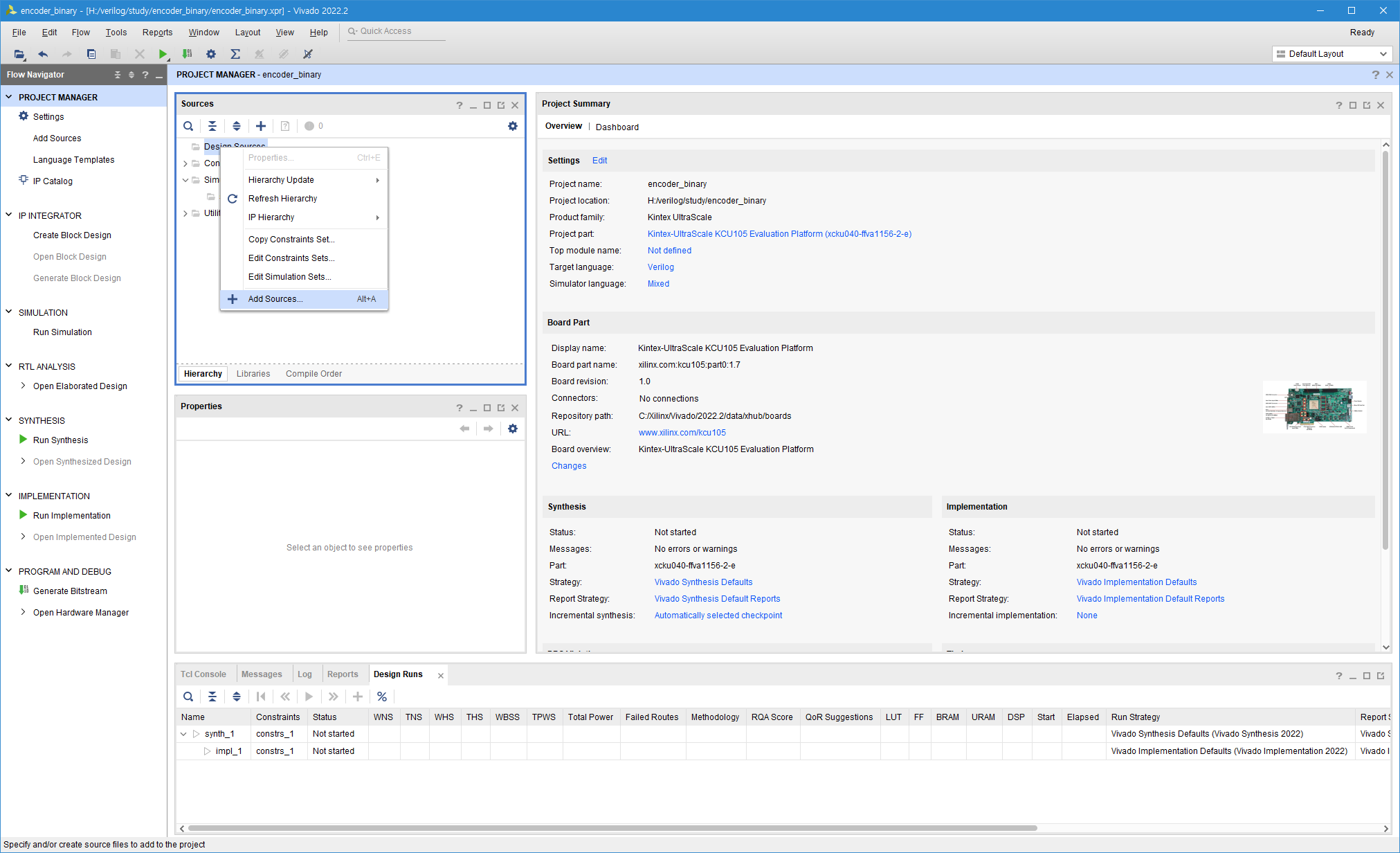
Design source 우클릭후 Add resource
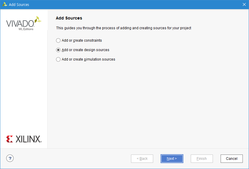
Next
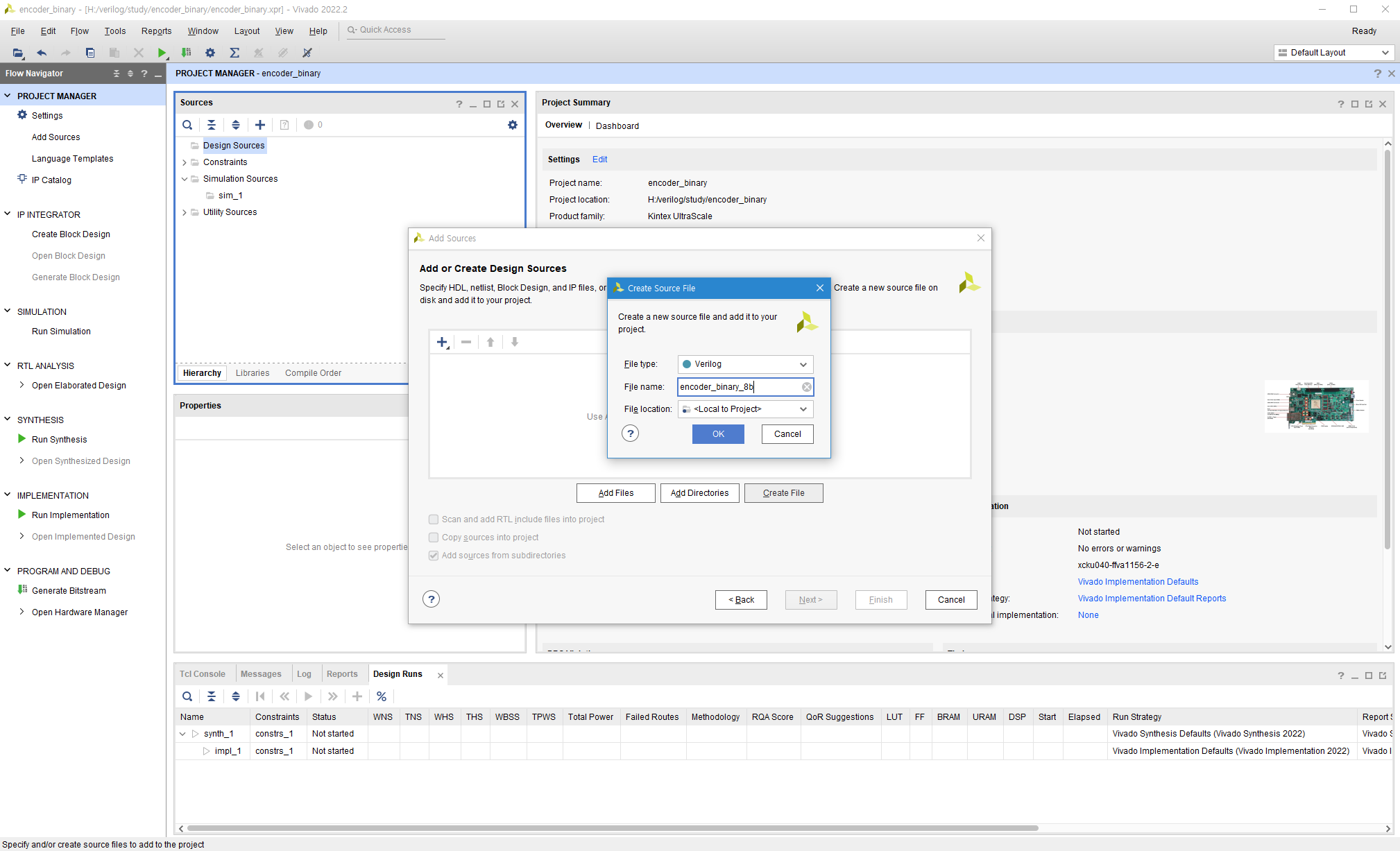
Verilog 파일(.v)명 작성
Next
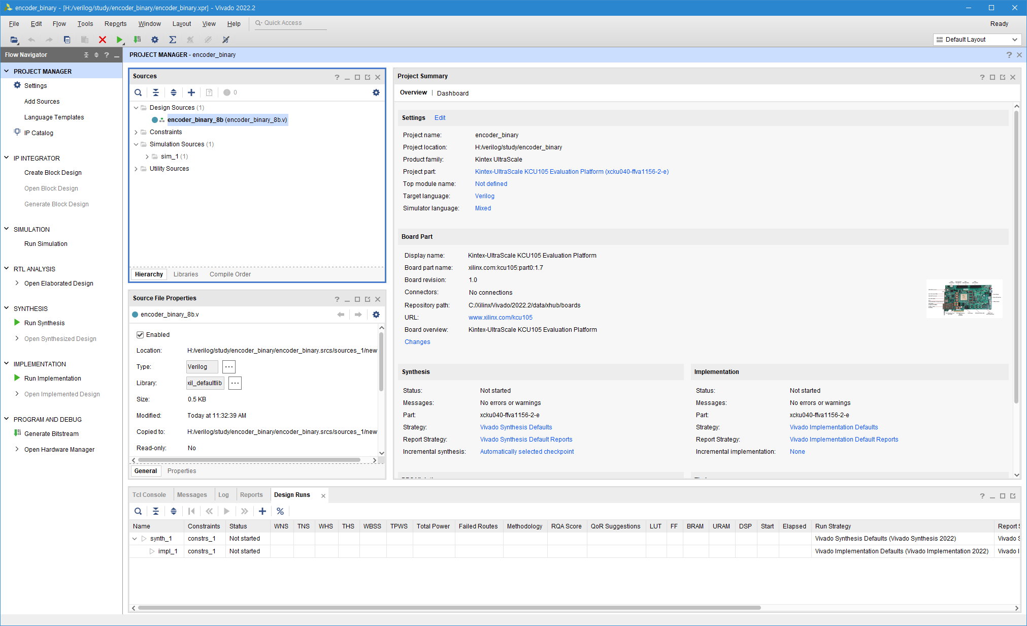
생성된 .V파일 더블 클릭
기본 탬플릿으로 작성된 .v 파일 생성 완료.
이후 Encoder설계를 진행한다. 이번 게시글에 사용할 인코더는 8-bit thermometer code를 4bit binary 로 변경하는 인코더이며 Clock 기반으로 동작하고 Rst 기능을 포함한다.
코드는 생성형 AI (Chat GPT 3.5를 이용하여 생성하였다. 생성한 코드는 다음과 같다.
`timescale 1ns / 1ps
module encoder_binary_8b(
    input clk,
    input rst,
    input [7:0] thermometer_in,
    output reg [3:0] binary_out
);

reg [7:0] stored_thermometer_in;

always @(posedge clk or posedge rst) begin
    if (rst) begin
        stored_thermometer_in <= 8'b00000000; // Reset stored input to all zeros
        binary_out <= 4'b0000; // Reset output to all zeros
    end else begin
        stored_thermometer_in <= thermometer_in;
        case(stored_thermometer_in)
            8'b11111111: binary_out = 4'b1000;
            8'b01111111: binary_out = 4'b0111;
            8'b00111111: binary_out = 4'b0110;
            8'b00011111: binary_out = 4'b0101;
            8'b00001111: binary_out = 4'b0100;
            8'b00000111: binary_out = 4'b0011;
            8'b00000011: binary_out = 4'b0010;
            8'b00000001: binary_out = 4'b0001;
            default: binary_out = 4'b0000; // Default case, when no input is active
        endcase
    end
end

endmodule
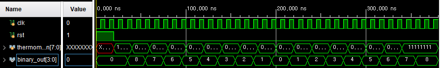
코드의 정상동작 여부를 확인하기위해 Test Bench를 생성하였다 Test Bench 생성법은 위의 encoder_binary_8b.v 파일 생성법과 같다. 테스트를 위해 초기에 Rst를 시키고 입력을 8에서 0까지,그리고 다시 0에서 8까지 Sweep 시키는 입력 데이터를 만들었다.
`timescale 1ns / 1ps

module thermometer_encoder_tb;

    // Parameters
    parameter CLK_PERIOD = 10; // Clock period in ns

    // Inputs
    reg clk;
    reg rst;
    reg [7:0] thermometer_in;

    // Outputs
    wire [3:0] binary_out;

    // Instantiate the unit under test (UUT)
    encoder_binary_8b uut (
        .clk(clk),
        .rst(rst),
        .thermometer_in(thermometer_in),
        .binary_out(binary_out)
    );

    // Clock generation
    always #((CLK_PERIOD/2)) clk = ~clk;

    // Testbench stimuli
    initial begin
        $dumpfile("thermometer_encoder_tb.vcd");
        $dumpvars(0, thermometer_encoder_tb);

        // Reset
        clk = 0;
        rst = 1;
        #20;
        rst = 0;

        thermometer_in = 8'b11111111; // Input 8
        #20;
        thermometer_in = 8'b01111111; // Input 7
        #20;
        thermometer_in = 8'b00111111; // Input 6
        #20;
        thermometer_in = 8'b00011111; // Input 5
        #20;
        thermometer_in = 8'b00001111; // Input 4
        #20;
        thermometer_in = 8'b00000111; // Input 3
        #20;
        thermometer_in = 8'b00000011; // Input 2
        #20;
        thermometer_in = 8'b00000001; // Input 1
        #20;
        thermometer_in = 8'b00000000; // Input 0
        #20;
        thermometer_in = 8'b00000001; // Input 1
        #20;
        thermometer_in = 8'b00000011; // Input 2
        #20;
        thermometer_in = 8'b00000111; // Input 3
        #20;
        thermometer_in = 8'b00001111; // Input 4
        #20;
        thermometer_in = 8'b00011111; // Input 5
        #20;
        thermometer_in = 8'b00111111; // Input 6
        #20;
        thermometer_in = 8'b01111111; // Input 7
        #20;
        thermometer_in = 8'b11111111; // Input 8
        #40;

        // Add more test cases as needed

        $finish;
    end

endmodule
시뮬레이션 결과 다음과 같이 정상적으로 binary 출력이 나오는것을 볼 수 있다.
'아날로그 연구실 > 디지털 설계' 카테고리의 다른 글
| (1) Auto Place & Routing을 해보자 - Introduction (0) | 2024.03.06 |
|---|